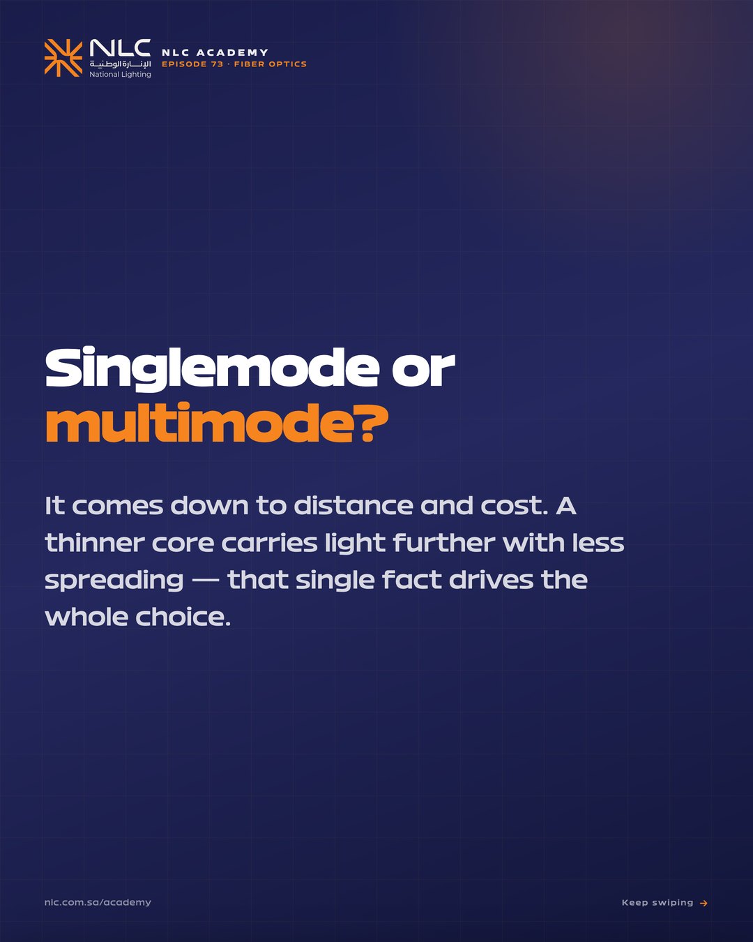
Cat6A reaches 100 m. Beyond that, the building runs on glass. OS2 singlemode for the WAN and risers, OM4 or OM5 multimode for the data hall, LC connectors for patch panels, MTP for high-density trunks. Here is the family tree of fiber and what each one is for.
Four ideas that close every fiber spec conversation.
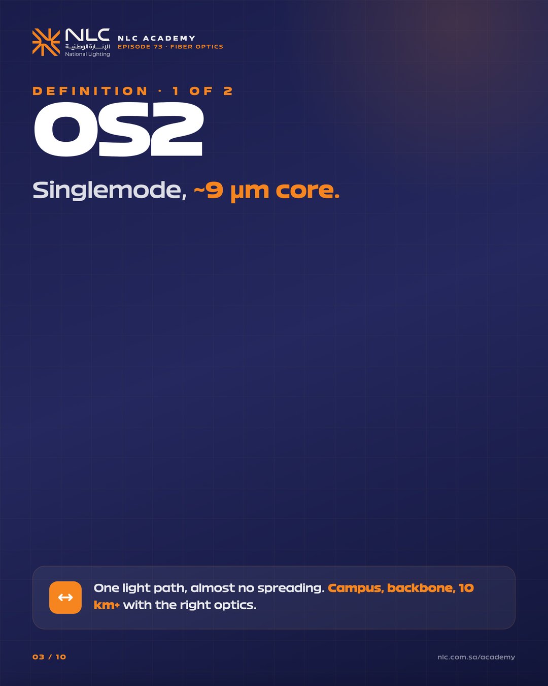
OS2 singlemode (9 µm core) goes 10 km+ on 10G; OM4 multimode (50 µm core) goes 150 m on 100G. Pick by distance, not preference.
OM1 (62.5/125 µm) is legacy. OM3 carries 10G to 300 m. OM4 to 400 m. OM5 (wideband multimode) supports SWDM for 40/100/400G on a single pair.
SC, ST, FC still exist for legacy. New installs are LC duplex for patch, MTP/MPO for high-density trunks. KSA datacenters standardise on LC + MTP-12 / MTP-24.
Mechanical splices are field-friendly but lossy (0.3–0.5 dB). Fusion splice is < 0.05 dB and permanent. OTDR traces find both faults and silent attenuation along the run.
ISO/IEC 11801 fiber categories.
| Class | Core / cladding | 10G reach | 100G reach | Use |
|---|---|---|---|---|
| OS1 / OS2 singlemode | 9 / 125 µm | 10–40 km | 10+ km | WAN · campus · riser |
| OM1 | 62.5 / 125 µm | 33 m | n/a | Legacy only |
| OM2 | 50 / 125 µm | 82 m | n/a | Legacy |
| OM3 | 50 / 125 µm | 300 m | 70 m | Data hall · standard |
| OM4 | 50 / 125 µm | 400 m | 150 m | Premium data hall |
| OM5 (WBMMF) | 50 / 125 µm | 400 m | 150 m + SWDM | 400G future-proof |
Six engineering decisions behind every fiber backbone.
A 9 µm core is narrow enough that only one optical mode propagates. No modal dispersion, no bandwidth-distance limit from mode mixing. The only limit is chromatic dispersion of the source, which 1310 / 1550 nm transceivers manage easily across 40 km.
A 50 µm core lets many modes propagate. Each mode arrives at a slightly different time, mode-dispersion. The standardised effective modal bandwidth (EMB) divided by reach gives the OM-class. Cheap VCSEL transceivers (850 nm) light it up at a fraction of singlemode optics cost.
Short-wavelength division multiplexing transmits four colours (850/880/910/940 nm) down one fiber. OM5 fiber holds bandwidth across all four. One pair becomes four channels, 100G becomes 400G without pulling new cable, the futureproof move on KSA Vision-2030 mega-projects.
LC (Lucent Connector) is small, push-pull, the modern default. SC (Square Connector) is bigger, latching, legacy. MTP/MPO carries 12, 24, or 48 fibers in one ferrule for high-density trunks. NLC structured-cabling solutions standardise on LC duplex at the rack and MTP-12 trunks between rooms.
UPC (Ultra Physical Contact) polish has 0.2 dB return loss. APC (Angled Physical Contact, 8°) hits 0.5 dB or better. APC is mandatory on singlemode WAN links and any analog-RF-over-fiber. Mixing UPC and APC ferrules damages both.
An Optical Time-Domain Reflectometer pulses light down the fiber and graphs reflections vs time. You see splice loss, connector loss, macro-bends, and breaks at exact metre positions. Every fiber link should ship with an OTDR trace as part of the as-built handover, both directions for symmetry verification.
NLC delivers OS2, OM4, and OM5 fiber infrastructure with LC and MTP termination, fusion-spliced, OTDR-tested, and warranty-backed to 25 years.
A 10-slide explainer, ready to post straight to LinkedIn as an image carousel. Same content, faster reading.
10 slides · LinkedIn-ready. Download all 10 as high-res PNGs and post them straight to LinkedIn as a carousel. PDF version still available.
Practical lighting know-how from NLC Academy. No spam, unsubscribe anytime.
By subscribing you agree to receive NLC emails.